By Julia Iv
A smartphone can fail without revealing much about what has gone wrong. Its screen stays black, charging produces no visible response, or the device restarts before it becomes usable. From the outside, these failures look like verdicts on the whole machine. Inside, however, the cause may be a damaged connector, a missing control signal, or a capacitor smaller than a grain of rice. The scale of the symptom tells us surprisingly little about the scale of the defect.
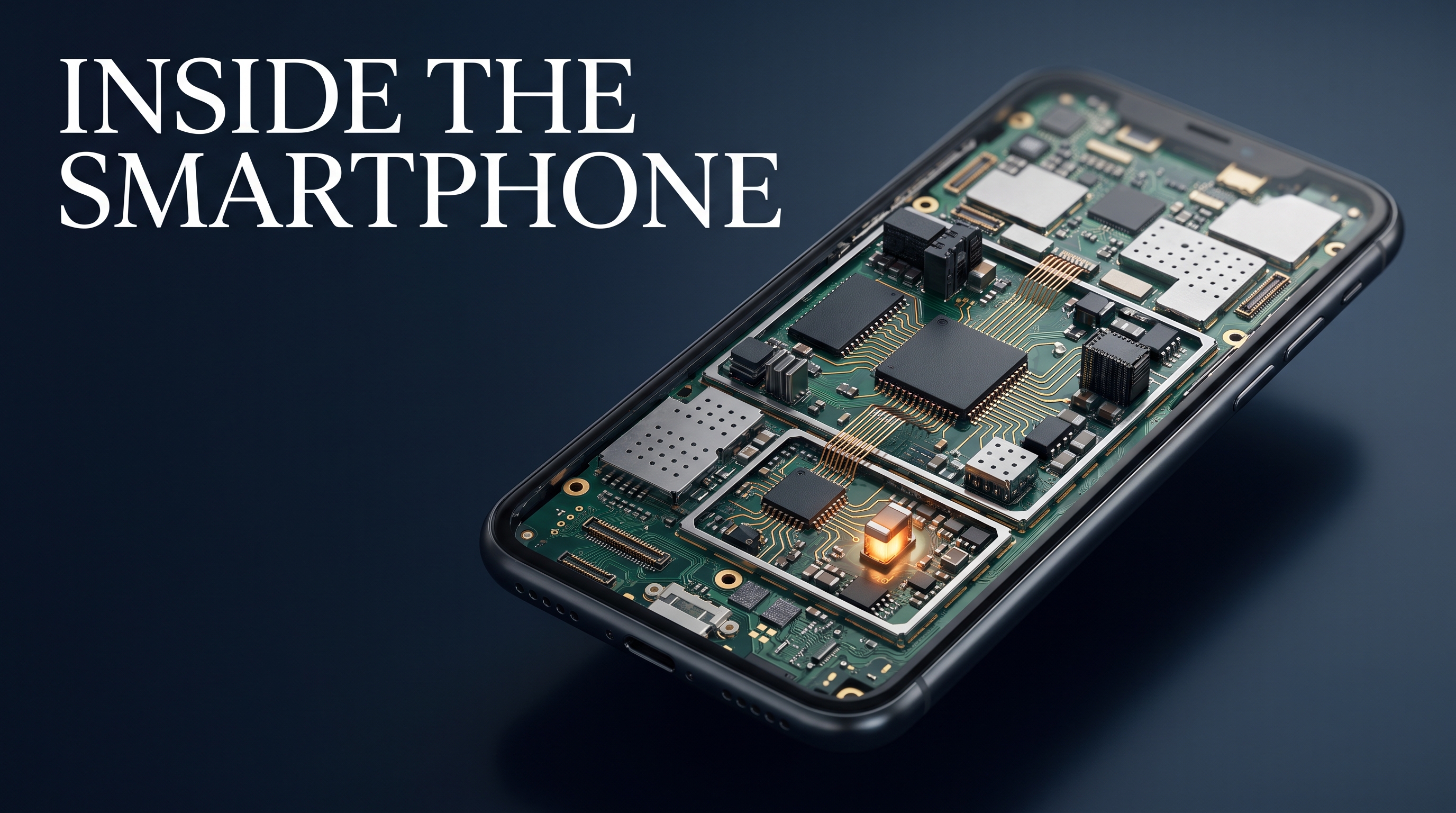
Understanding that mismatch begins with the logic board. Beneath the display is an assembly in which electrical, mechanical, and thermal functions occupy much of the same space. Power must reach the right circuits at the right time. Signals must arrive with sufficient integrity to be understood. Heat must escape, and connections must survive everyday movement. A phone works because these conditions hold together; diagnosing it means discovering where that agreement has broken down.
The main logic board carries much of the phone’s computing and control hardware: its application processor, memory and storage, power-management circuits, and portions of its audio and radio systems. Yet the working device extends beyond that board. Depending on the model, smaller daughterboards may carry the charging port, microphones, or antenna connections. Flexible cables connect displays, cameras, buttons, and other modules. Miniature coaxial cables carry radio-frequency signals between sections of the wireless system.
Even apparently ordinary structural details can participate in the circuit. Spring contacts and parts of the frame can provide grounding or antenna connections. Metal shields limit electromagnetic interference, while thermal materials help transfer heat away from concentrated sources. A displaced contact or damaged flex cable can therefore interrupt a function even when the major chips remain intact. The physical assembly is part of the electrical design.
The board itself also contains more than its surface reveals. Copper conductors and insulating materials form a multilayer structure, with internal routes carrying power and signals beneath visible components. Ground planes provide reference potentials and return paths; power planes and copper pours distribute energy. Small plated connections called vias link the layers. As Cadence explains in its guide to PCB vias, microvias make the dense routing required by smartphone components possible. Much of the network that determines whether a device works is consequently hidden within the board rather than exposed on it. [1]
Some designs take this compression further by stacking board sections. In its iPhone X teardown, iFixit documented a logic-board assembly that effectively folded the available circuitry into a smaller footprint by soldering two sections together. That design illustrates a recurring engineering tradeoff: space saved inside the product can become additional complexity during repair. Connections between stacked sections are difficult to inspect, and accessing them requires more than removing an outer shield. [2]
This physical density matters because a phone has many distinct electrical needs. The battery does not simply deliver one usable voltage to every component. Regulators convert incoming power into multiple supply voltages for the processor, memory, cameras, display, radios, and other circuits. These supplies are commonly called power rails. Each rail serves particular loads, and some become active only when the device enters a state that requires them.
Starting the phone is therefore a sequence of dependencies. An always-on circuit may first detect a wake request, after which additional supplies, clocks, and control signals become available. Later stages depend on earlier ones meeting their conditions. A rail that is absent may indicate a failed regulator, but it may also indicate that the regulator has not received permission to turn on. The distinction changes the diagnosis completely: replacing the component that supplies power cannot restore a command that never reaches it.
The same caution applies when interpreting resistance measurements. A low resistance to ground can suggest a short circuit, but there is no universal threshold that makes the diagnosis valid for every rail. Processor supply networks can legitimately measure very low because of the circuitry connected to them. Capacitors can also influence the reading while they charge from the meter; their transient behavior should not be confused with a persistent short. Meaningful interpretation depends on the rail, measurement polarity, instrument, and board condition. A working board of the same model provides a far more useful reference than an isolated number.
Among the smallest components, capacitors have an especially disproportionate influence. They help stabilize local supplies and filter disturbances. A ceramic capacitor that cracks and shorts can pull down a shared rail, potentially preventing the phone from starting. An absent or damaged decoupling capacitor may instead contribute to instability that appears only under particular loads. In either case, the visible failure can seem far more serious than the component responsible for it.
Other small parts establish equally important conditions. Resistors set bias levels, pull control lines toward defined states, and participate in current sensing. An open resistor may leave a circuit without a valid instruction or measurement. Inductors store energy in switching converters, while ferrites and filters help control interference along power and signal paths. A broken connection through one of these parts can disable a particular function while leaving neighboring circuits apparently healthy. Their diagnostic significance comes from their position in the circuit, not their physical size.
Larger integrated circuits bring their own ambiguity. A power-management chip generates and coordinates supplies, but an overloaded output or a shorted downstream component can make a healthy chip appear defective. Charging faults may involve the port, cable, protection devices, switching components, or interface controller. The symptom identifies a part of the system worth investigating; it does not identify the replacement part. This is why a diagnosis such as “power IC failure” needs evidence from the surrounding circuit.
Wireless problems extend that reasoning beyond power distribution. Cellular communication depends on a chain that includes modem processing, transceivers, amplifiers, filters, switches, antenna tuning, and physical antenna connections. Qualcomm’s RF front-end overview describes the range of functions concentrated in this part of a phone. A weak signal can originate along that hardware path, while network conditions or software introduce other possibilities. A damaged antenna contact can resemble a deeper radio failure because both ultimately affect the same experience: the phone cannot maintain a reliable connection. [3]
Memory and storage introduce another set of dependencies. RAM provides working space during operation, while nonvolatile storage retains software and user data. Failures involving either can interrupt startup or cause instability. On many modern devices, encryption also ties access to user data to hardware-backed security mechanisms and credentials. Making a storage chip electrically readable is consequently a different achievement from recovering usable files. Repairing the device and recovering its contents can require preserving different parts of the original system.
The application processor sits at the center of many of these relationships, which makes it an easy suspect when a phone will not boot. Yet missing power, an incorrect reset state, an absent clock, or a damaged connection can prevent a healthy processor from operating. Solder joints beneath the package may also be involved. “Processor failure” is a conclusion to establish after examining its dependencies, rather than a useful label for every unexplained startup problem.
Measurements help separate these possibilities, provided their limits remain clear. A multimeter can reveal continuity, static voltages, and resistance patterns. It cannot establish that every high-speed signal carries valid information. An oscilloscope can reveal timing, supply ripple, or activity on accessible lines, although probe access, bandwidth, and the measurement setup constrain what can be learned. A voltage that appears correct in a static reading may behave differently during startup or a sudden increase in load.
Physical intervention adds further constraints. Many packages hide their solder connections underneath them, and some use reinforcing adhesive known as underfill. Shields obscure nearby components, while dense layouts leave little space for rework. Heating or removing one part can disturb another. The challenge is to reach the suspected fault while preserving the surrounding assembly and the connections that still work.
The practical consequence is that diagnosis must follow relationships. A black screen does not establish that the board has stopped running. A restart does not establish that the processor is defective. A missing supply does not, by itself, establish that its regulator has failed. Each observation becomes useful when it narrows the next question: whether power is available, whether startup is progressing, whether a peripheral responds, or whether a signal can cross an interface.
The smartphone’s remarkable compactness makes these relationships easy to overlook. Seen from outside, it is one object with a handful of recognizable functions. Inside, those functions depend on a tightly arranged network of supplies, controls, data paths, and physical contacts. A tiny defect can silence the whole device because it interrupts something many other circuits require. Understanding the logic board makes that failure less mysterious and makes the search for its cause more precise.
Sources
[1] Cadence, “What Is a PCB Via?”.
[2] Kyle Wiens, iFixit, “Teardown: Inside the iPhone X”, November 3, 2017.
[3] Qualcomm, “RF & RF Front End (RFFE)”.
Julia Iv / Technology & Human Life
Inside the smartphone: why a tiny fault can silence an entire device
From Julia Iv
IT Cabin
He lost the career that defined him. Then he disappeared into a cabin.
Follow on Amazon